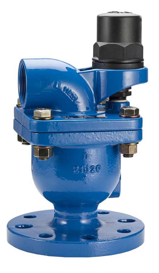
AVK COMBINATION AIR VALVE
PN 10/16

Jack Waddle
External Sales Engineer Smart Water & Pressure Management
Combination air relief valve Maximum Working Pressure: 16 Bar. Temperature Range: -10°C to +70°C. Insulation essential for temperatures of 0°C and below. Hydraulic test. Seat: 1.0 x PN high. 0.2 Bar. low. Body: 1.5 x PN. Inlet flange to BS EN 1092-2: 1997
AVK combination air valves are combined automatic and air vacuum valves. The automatic air release function releases accumulated air from the system while it is under pressure. The air and vacuum function discharges and admits large volumes of air during the filling or draining of pipelines. The valve will open to relieve negative pressures whenever water column separation occurs.
| Variant 701/50-001 | |
|---|---|
| Connection: | Flanged |
| Material: | Ductile Iron |
| DN: | DN50 - DN200 |
| PN: | PN 16 |
Features
- Releases large volumes of air from pipelines up to 0.9 bar. Discharge from the small orifice is 10 times greater than from conventional units.
- Orifice sizes:
Air and vacuum DN 100: 3317 mm² – automatic 12 mm²
Air and vacuum DN 150: 7850 mm² – automatic 12 mm²
Air and vacuum DN 200: 17662 mm² – automatic 12 mm² - The enlarged orifice is less exposed to obstruction by debris
- The orifice in the automatic valve releases large volumes of air at high flow rates when the line is under pressure
- The automatic valve’s rolling seal mechanism design is less sensitive to different pressures than a direct float seal, thus enabling a one size orifice for a wide pressure range
- Reliable operation reduces water hammer incidents
- Dynamic design allows for high velocity air discharge while preventing premature closure
- Special orifice seat design with a combination of bronze and EPDM rubber ensures long-term maintenance-free operation
- The discharge outlet enables removal of excess fluids
- Air and vacuum air valve with body and cover of ductile iron with blue fusion bonded epoxy coating in compliance with DIN 3476 part 1 and EN 14901
- Automatic valve of high-strength composite material. Lightweight design, corrosion resistant construction.
- Float of polycarbonate
- With connection flange or BSP thread
Downloads
Reference nos. and dimensions:
| Ref. no. | DN mm |
Connection |
PN Class test |
L mm |
H3 mm |
C mm |
Theoretical weight/kg |
|---|---|---|---|---|---|---|---|
| 701-050-50-41003 | 50 | 50mm | PN16 | 173 | 293 | 1 1/2" BSP | 9.0 |
| 701-058-50-41003 | 80 | 50mm | PN16 | 173 | 293 | 1 1/2" BSP | 17 |
| 701-080-50-41003 | 80 | PN16 | 17 | ||||
| 701-100-50-41003 | 100 | PN16 | 28 | ||||
| 701-150-50-41003 | 150 | PN16 | 78 | ||||
| 701-200-50-41003 | 200 | PN16 | 86 |
Components
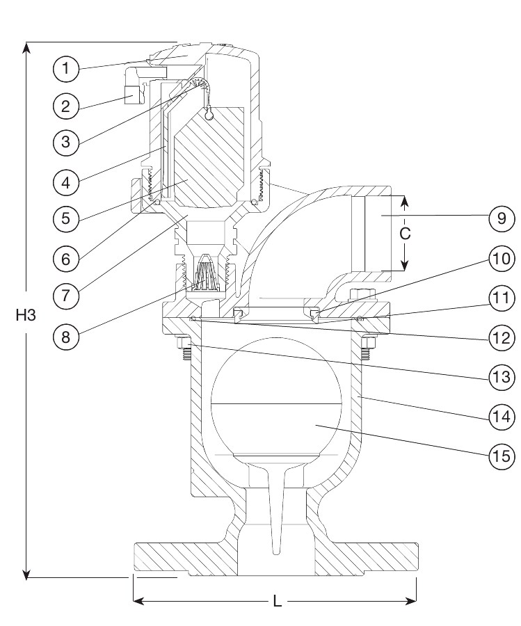
| 1. | Body | Reinforced PA |
| 2. | Discharge outlet | PP |
| 3. | Rolling seal | EPDM |
| 4. | Clamping Key | Reinforced PA |
| 5. | Float | Foamed PP |
| 6. | O-ring | NBR rubber |
| 7. | Base | Reinforced PA |
| 8. | Strainer | PA |
| 9. | Cover | Ductile iron |
| 10. | Orifice seat | Bronze |
| 11. | Orifice seat | EPDM |
| 12. | O-ring | NBR rubber |
| 13. | Bolt assembly | Steel |
| 14. | Body | Ductile iron |
| 15. | Float | PC |
Test/Approvals
- WRAS approved Product
Standards
- Designed according to BS
- Standard flange drilling to EN1092 (ISO 7005-2), PN 16
- Seat: 1.0 x PN high. 0.2 Bar. low. Body:1.5 x PN.