AVK UNDERGROUND AIR VALVE, PN10
For wastewater, complete air valve assembly, high or low

Jack Waddle
External Sales Engineer Smart Water & Pressure Management
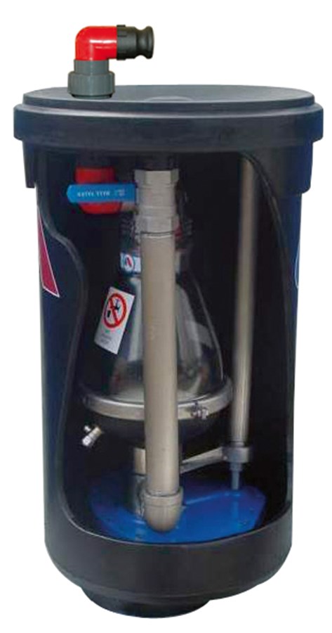
Underground air valve system - Chamber height 1080 mm - Total height 1175 mm, for wastewater treatment to max. 60°C (temporarily up to 90°C)
AVK underground system offers convenient and fast access to maintenance from ground level by lifting the complete valve assembly out of the external box. The combination air valve is dedicated for wastewater and designed to combine large volume of air discharge/intake whilst filling/draining a pipeline with automatic discharge of air deliberated from the fluid. The air valve features an innovative design with a large air gap between liquid and sealing system.
| Variant 701/79-011 | |
|---|---|
| Connection: | External BSP Thread |
| DN: | DN80 - DN100 |
| PN: | PN 10 |
| Closing direction: | Clockwise to Close |
Features
- Corrosion resistant and light-weight materials with external PE box and drainage assembly/connections of polypropylene and other main parts of stainless steel
- The system can be back flushed on site
- When maintenance is needed the pressure is released by means of the ball valve, the knife gate shut-off valve is closed by means of the T-key, and the complete assembly is taken out for service or maintenance
- Easy usage with quick connectors on both the inlet and outlet flushing positions
- Built-in safety, as it is not possible to extract the air valve unless the shut-off valve is closed and the internal pressure is released
- Air valve orifice sizes: Automatic 12 mm2, kinetic 804 mm2 (Air valve series 701/75)
- The large orifice in the automatic valve releases large volumes of air when the line is under pressure. The spring between the stem and upper float compensates for slight pressure changes
- The float system of polypropylene and stainless steel ensures high corrosion resistance
- The conical body with funnel-shaped lower body allows maximum air volume within minimum valve length and prevents accumulation of deposits at the bottom
- An exhaust tube can be mounted in the threaded opening on the top of the valve
- With connection flange or 3” BSP thread
- Working pressure range 0.05 - 10 bar
Downloads
Reference nos. and dimensions:
| Ref. no. | H mm |
H3 mm |
W mm |
Theoretical weight/kg |
Notes |
|---|---|---|---|---|---|
| 701-080-79-190010 | 870 | 970 | 448 | 38 | 3" thread, nylon |
| 701-081-79-190010 | 870 | 970 | 448 | 38 | 3" thread, stainless steel |
| 701-082-79-190013 | 870 | 970 | 448 | 38 | 3" flanged, nylon |
| 701-083-79-190013 | 870 | 970 | 448 | 38 | 3" flanged, stainless steel |
| 701-084-79-190010 | 1075 | 1170 | 448 | 39 | 3" thread, nylon |
| 701-085-79-190010 | 1075 | 1170 | 448 | 39 | 3" thread, stainless steel |
| 701-086-79-190013 | 1075 | 1170 | 448 | 39 | 3" flanged, nylon |
| 701-087-79-190013 | 1075 | 1170 | 448 | 39 | 3" flanged, stainless steel |
| 701-100-79-190013 | 870 | 970 | 448 | 38 | 4" flanged, nylon |
| 701-101-79-190013 | 870 | 970 | 448 | 38 | 4" flanged, stainless steel |
| 701-102-79-190013 | 1075 | 1170 | 448 | 39 | 4" flanged, nylon |
| 701-103-79-190013 | 1075 | 1170 | 448 | 39 | 4" flanged, stainless steel |
Components
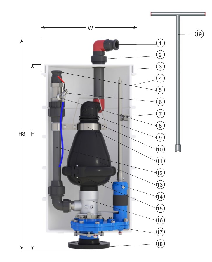
| 1. | Discharge outlet | PP |
| 2. | Coupling | PVC |
| 3. | Cover | PE |
| 4. | Air valve box | PE |
| 5. | Drain outlet | PE |
| 6. | Pressure relief ball valve | Stainless steel 316 |
| 7. | Shut-off valve extension | Stainless steel |
| 8. | Ball valve | Stainless steel 304 |
| 9. | Rolling seal | EPDM/PA/SS |
| 10. | Float | Foamed PP |
| 11. | Bridge assembly | Stainless steel |
| 12. | Back flushing drainage | PP |
| 13. | Body | Reinforced PA |
| 14. | Base | Reinforced PA |
| 15. | Float | Foamed PP |
| 16. | Adaptor | Stainless steel 316 |
| 17. | Knife shut-off valve | Ductile iron |
| 18. | Flange | Reinforced PA |
| 19. | T-key | Stainless steel |
Test/Approvals
- Hydraulic test according to EN 1074-1 and 4 / EN 12266.
- Approved for wastewater