AVK UNDERGROUND FIRE HYDRANT, SQUAT TYPE, PN 16
DN80

Mamoun Humayra
Water Product Manager
Underground fire hydrant squat type for water and fire protection to max. 70° C. Temperature Range: -10°C to +70°C, Insulation essential for temperatures of 0°C and below.
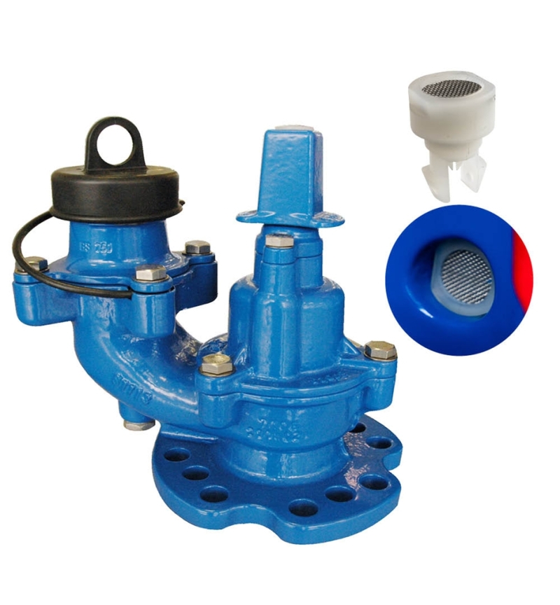
The Series 29/388 is a squat fire hydrant suitable for use with water and neutral liquids, to a maximum temperature of 70°C. Complies with requirements of BS 750 and BS EN1074-2:2000 and EN 14339:2005, underground hydrants. Also to BS EN 1074-6 for potable (drinking) water.
| Variant 29/388-001 | |
|---|---|
| Connection: | No connection type specified |
| Material: | Ductile Iron |
| DN: | DN80 - DN80 |
| PN: | PN 16 |
| Closing direction: | Clockwise to Close, Stem Cap/White Insert |
Features
- Inlet flange universally drilled to EN1092-2 PN10/16 and BS10 TableD/E.
- BS 750 Type 2c. Screwed -down type with screwed 2½” round thread outlet. Auto-frost drain valve as standard. Fixed stopper.
- Complies with Annex ZA of BS EN 14339 in respect of Construction Products Directive (CPR)(EU) 305/2011.
- Fully maintainable. Low weight design.
- 2½” London round thread outlet to BS 750.
- Exceeds flow requirements: Kv = 92 minimum 2000l/min @1.7 bar. Actual: Kv = 96, 2092 l/min @1.7 bar.
- Upgraded frost plug design with built in SS316 mesh and an improved fit reduces debris related failures and prevents plug push through, while remaining fully compatible with existing replacement procedures.
- Corrosion resistant construction, ductile iron coated with WRAS approved epoxy coating Blue RAL 5017, to 250 microns min. Internal holiday-free coating, compliant with BS EN 1074-6 for disinfection products.
- Note: It is recommended that applications in a corrosive atmosphere or sited in exposed locations use a stainless steel stem 1.4404 (316) and all exposed fasteners in A4 stainless steel. Product reference S.29/389.
- Options:
- PN25 version, Loose stopper available, Outlet options: • Stainless steel (standard) or Gunmetal to BS 750 round thread • Instantaneous (Morris) • Belfast • London “V” thread • Internal screwed Norwegian • Bayonet (Dublin).
Downloads
Datasheet
Related Datasheets
Appendix
Certificate(s)
Installation, Operation & Maintenance
Flyer
Price list
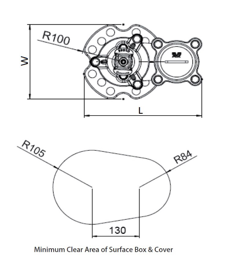
Reference nos. and dimensions:
Scroll for more info
| Ref. no. | PN Class test |
DN mm |
H mm |
H3 mm |
L mm |
L1 mm |
W mm |
W5 mm |
Theoretical weight/kg |
E.C.* kg |
Notes |
|---|---|---|---|---|---|---|---|---|---|---|---|
| 29-388-3-2112 | PN16 | 80 | 278 | 284 | 283 | 102 | 190 | 127 | 13 | 28.6 | Fixed Stopper |
| 29-388-3-211201 | PN25 | 80 | 278 | 284 | 283 | 102 | 190 | 127 | 13 | 28.6 | Fixed Stopper |
| 29-388-3-72120006 | PN16 | 80 | 278 | 278 | 283 | 102 | 190 | 127 | 13 | 28.6 | Loose Stopper |
| 29-388-3-72120106 | PN25 | 80 | 278 | 284 | 283 | 102 | 190 | 127 | 13 | 28.6 | Loose Stopper |
3D drawings
Enquiry
Scroll for more info
Components

| 1. | Body | Ductile Iron GJS-500-7 |
| 2. | Body-bonnet seal | NBR rubber |
| 3. | Fasteners | Stainless steel A2 |
| 4. | Stopper Assembly | Ductile Iron GJS-500-7 |
| 5. | Bonnet | Ductile Iron GJS-500-7 |
| 6. | Thrust collar | Brass CW602N |
| 7. | Gland flange | Ductile Iron GJS-500-7 |
| 8. | Stem Cap | Ductile Iron GJS-500-7 |
| 9. | Stem | Stainless steel 1.4021 |
| 10. | Seal | NBR rubber |
| 11. | Dust Cap | PE |
| 12. | Outlet | Stainless steel 1.4021 |
| 13. | Body-outlet Seal | NBR rubber |
| 14. | Auto-Frost Valve |
Test/Approvals
-
Seat: 1.1 x PN (in Bar), Body: 1.5 x PN (in Bar). Closing torque test.
- Approved according to Kitemark™ 53897 BS750 and EN 14339
- Drinking Water Inspectorate Regulation 31 compliant
- UKCA / CE marked according to Construction Products Directive
- Made in Great Britain
Standards
- Designed according to BS750, EN 1074 part 1 & 2, Designed according to EN 14339:2005
- Double drilled PN10/16 and BS10 table D (only DN80 and DN100)