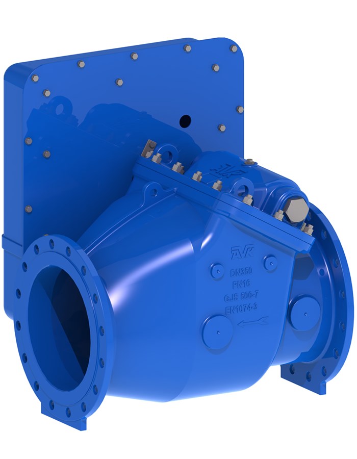
SWING CHECK VALVE, METAL SEAT, PN10/16
Lever/weight RH side, horiz. inst., alu-bronze seat, brass-bushings, EN 558/48 with plastic guard and bracket, SS shaft, A2 bolts, EPDM, 250µm blue EP coating

Jack Waddle
Product & Solutions Manager – Air Valves & NRVs
Check valve for drinking water and neutral liquids incl. treated waste water free of solids and fibrous impurities to max. 70°C, horiz. inst.
AVK series 41 swing check valves come with both metal and resilient seats to be installed in pumping applications to prevent back flow. The disc is connected to the shaft via a flexible bush that allows disc and valve seat to adjust exactly and secure a tight seal. All interior parts are stainless steel or coated with drinking water approved epoxy. Rubber parts are hydrocarbon resistant NBR or drinking water approved EPDM. The series 41 valves are available with either enclosed shaft end or protruding shaft end where a lever with a weight or a spring can be fitted to mitigate pressure surges.
| Variant 41/36-007 | |
|---|---|
| Connection: | Flanged |
| Material: | Ductile Iron |
| DN: | DN350 - DN600 |
| PN: | PN 16 |
Features
- Body and bonnet in ductile-iron
- Metal seat in alu-bronze for high durability. The light weight of the disc requires a minimum of force to open
- Disc mounted on a flexible rubber bushing allowing it to tilt slightly in all directions and adjust exactly to the valve seat
- Shaft material stainless steel
- Stainless steel grade A2 bolts
- Disc core fully vulcanized with drinking water approved EPDM
- All seals in contact with the water in drinking water approved EPDM
- Bonnet gasket fixed in a groove between bonnet and body to prevent blow-out
- Shaft end fitted with a position indicating lever and weight to assist valve closing and avoid water hammer
- The lever mechanism is protected by a plastic guard.
- 250µm fusion bonded blue RAL5017 epoxy coating, approved for drinking water
- Bosses on each side of the valve seat allow for installation of pressure gauge, by-pass, etc.
- Shaft fitted in the bonnet allowing for easy maintenance without removing the valve from the pipeline
Downloads
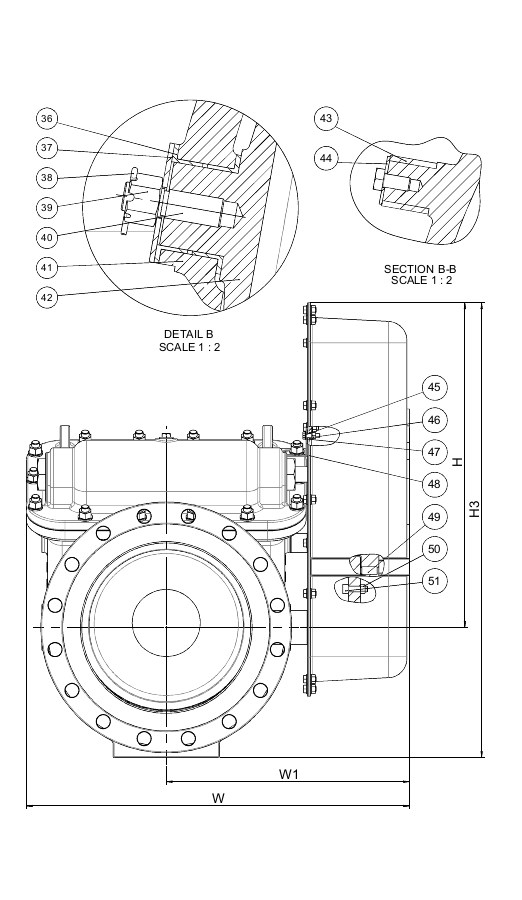
Reference nos. and dimensions:
| Ref. no. | DN mm |
Flange drillling |
L mm |
H mm |
H3 mm |
W mm |
W1 mm |
Theoretical weight/kg |
|---|---|---|---|---|---|---|---|---|
| 41-350-36-0180060 | 350 | PN16 | 800 | 673 | 943 | 794 | 499 | 269 |
| 41-400-36-0180060 | 400 | PN16 | 900 | 717 | 1012 | 864 | 539 | 358 |
| 41-450-36-0180060 | 450 | PN16 | 1000 | 852 | 1177 | 933 | 573 | 497 |
| 41-500-36-0180060 | 500 | PN16 | 1100 | 882 | 1247 | 996 | 606 | 660 |
| 41-600-36-0180060 | 600 | PN16 | 1300 | 947 | 1377 | 1110 | 663 | 869 |
Components
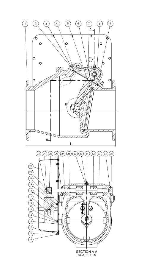
| 1. | Body | Ductile Iron GJS-500-7 |
| 2. | Washer | Stainless steel A2 |
| 3. | Nut | Stainless steel A2 |
| 4. | Stud bolt | Stainless steel A2 |
| 5. | Face ring | Alu-bronze CC331G (AB1) |
| 6. | Seat ring | Alu-bronze CC331G (AB1) |
| 7. | Bonnet | Ductile Iron GJS-500-7 |
| 8. | Bolt | Stainless steel A2 |
| 9. | O-cord | EPDM |
| 10. | Bolt | Stainless steel A2 |
| 11. | Washer | Stainless steel A2 |
| 12. | Nut | Stainless steel A2 |
| 13. | Spacer | PA |
| 14. | Guide bracket | Carbon steel |
| 15. | Bolt | Stainless steel A2 |
| 16. | Bolt | Stainless steel A2 |
| 17. | Weight | Ductile Iron GJS-500-7 |
| 18. | Guard back plate | ABS |
| 19. | Washer | Stainless steel A2 |
| 20. | Bolt | Stainless steel A2 |
| 21. | Spacer washer | PA |
| 22. | Guard front plate | ABS |
| 23. | Bolt | Stainless steel A2 |
| 24. | Washer | Stainless steel A2 |
| 25. | Lever | Ductile Iron GJS-500-7 |
| 26. | O-ring | EPDM |
| 27. | Bushing, open | Brass CW602N (CZ132) |
| 28. | O-ring | EPDM |
| 29. | Gasket | PA |
| 30. | Air plug | Stainless steel |
| 31. | Shaft | Stainless steel 1.4021 (420) |
| 32. | Connector | Stainless steel 1.4408 |
| 33. | Spacer | Stainless Steel 1.4401 (316) |
| 34. | O-ring | EPDM |
| 35. | Bushing, closed | Brass CW602N (CZ132) |
| 36. | Guide bush | EPDM |
| 37. | Washer | Stainless steel A2 |
| 38. | Split pin | Stainless steel A2 |
| 39. | Castle nut | Stainless steel A2 |
| 40. | Stud bolt | Stainless steel A2 |
| 41. | Hinge arm | Ductile Iron GJS-500-7 |
| 42. | Disc | Ductile Iron GJS-500-7 |
| 43. | Protective bush | EPDM |
| 44. | Washer | Stainless Steel 1.4401 (316) |
| 45. | Bolt | Stainless steel A2 |
| 46. | Nut | Stainless steel A2 |
| 47. | Washer | Stainless steel A2 |
| 48. | Bracket | Stainless steel 316 |
| 49. | Set screw | Stainless steel A2 |
| 50. | Nut | Stainless steel A2 |
| 51. | Bolt | Stainless steel A2 |
Test/Approvals
- Hydraulic test according to EN 1074-1 / EN 12266 |
- Seat: 1.1 x PN. Body: 1.5 x PN.
Standards
- Designed according to EN 1074 - 3
- Face to face according to EN 558 Table 2 Basic Series 48
- Standard flange drilling to EN1092, PN 10/16
- WIMES 8.09 Compliant
- Drinking Water Inspectorate Regulation 31 compliant